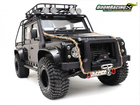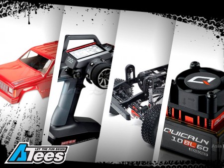
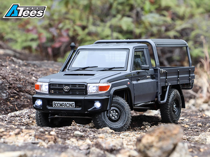
How To Build A Custom Scale Chassis For The Toyota LC70
If you’ve been following some of the latest builds on the internet, or have to opportunity to trail with friends or go to local comps recently, chances are you’ve seen a scale Toyota LC70. There are now many videos on YouTube and hundreds of photos on the internet of very realistic looking Land Cruisers. Have you considered building one yourself? If you’re looking to build a chassis that will fit the Killerbody LC70 body, but not sure where to start, here is a full guide on how I’ve done it. I had in mind to keep the cost low so it can be affordable for everyone. I will try my best to explain and show in pictures how all these things fell in place to achieve the result.
The Build Starts
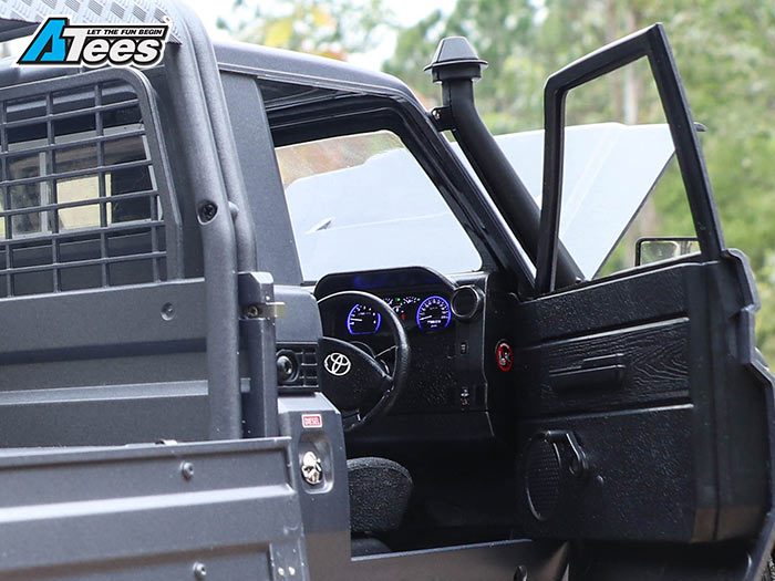
With the Killerbody LC70 hard body set on hand, all the parts that need to be painted are trimmed out first. I prepared them all ready for painting by sanding down all the mold lines and washed the releasing agent off with some soap and water. After all the parts are washed, I made sure they are all dry so that they are ready to be painted. Once everything is prepped I then painted up the parts in the chosen colors. Next is to assemble the body by following the instruction manual, including all of the optional body accessories. For more information on how and what I used for the body, this blog it has a step-by-step guide on how the body was built.
The Chassis Selection
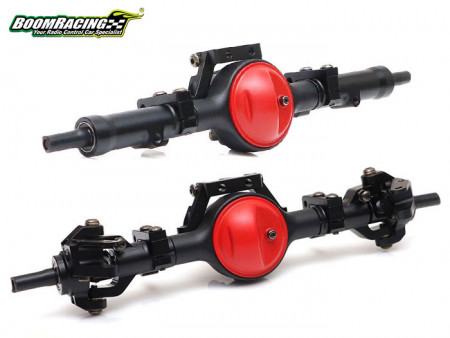
For the chassis I decided to use the MST CFX (MST/532148). We’ve had good experiences with this platform. The overall quality is good and it is a good performance chassis. Parts are laid out in the configuration that I was looking for; namely having a front motor transmission and narrow axles. I wanted to use the CFX axles because of the narrow width which tuck nicely inside the wheel wells. Having the right axle width is the key for this build.
There are a few additional parts I needed to get. The CFX is an adjustable short wheelbase chassis at 242/252/267mm which is too short for the 313mm wheelbase LC70 body, so the chassis needs to be extended. I did that by getting the CFX-W chassis rails (MST/310093) as they are the right length and all the mounting holes are in the same positions for an easy swap.

Links & Drive Shafts
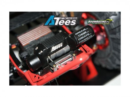
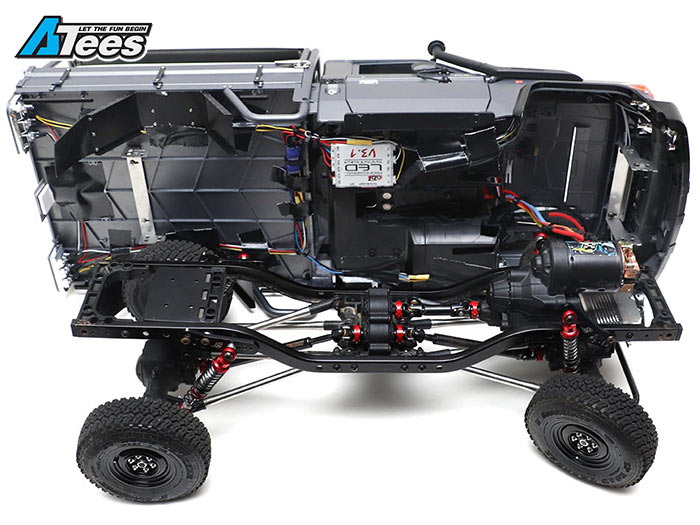
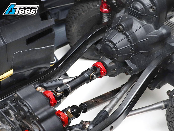
After the main chassis parts like the gearbox and the transfer case are assembled, I mounted them onto the CFX-W chassis rails. I kept the skid plate and transfer case in the same location as stock. The transmission and gearbox had to be moved forward so that I didn't have to trim too much off from the LC70 interior. By moving the gearbox forward a longer driveshaft is needed to connect the gearbox to the transfer case. I used a Boom Racing Voodoo Shaft (BRQ90279B) for this. A few milliliters were filed down of both ends to make it an even snug fit.
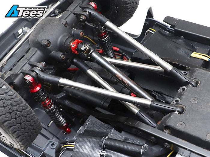
Next I assembled the front and rear axles to get them ready for the chassis. To mount them onto the chassis I got the Boom Racing 313mm Stainless Steel Links Set for the CFX-W (BR967010S) as it has the desired 313mm wheelbase length. I tweaked the links slightly with different rod ends till the perfect wheel alignment was found to the wheel arches / fenders. The links are also a good upgrade over stock as they are heavier, adding some nice down low weight for lower center of gravity performance. The link set uses M4 threads instead of the M3 threads that come with the kit, which provides more strength and durability.
I used an additional packet of stainless steel mixed rod ends (BRWM4RECOMBO). This gave me good adjustability options to fine tune the wheelbase for a better fit. The rod ends turned out handy, they are durable and great for custom adjustments. The pivot balls are stainless steel, which will prevent rust buildup that might cause binding and/or prevent smooth rotation.
What rod ends to use with which links:
- Front Upper Link Rod End – 1x Long Straight (21.8mm) & 1x Long Upwards (23.5mm)
- Rear Upper Link Rod End – 1x Short Straight (18.5mm) & Short Upwards (20mm)
- Front Lower Link Rod End – 1x Long Straight (21.8mm) & Long Upwards (23.5mm)
- Rear Lower Link Rod End - 1x Short Straight (18.5mm) & Short Upwards (20mm)
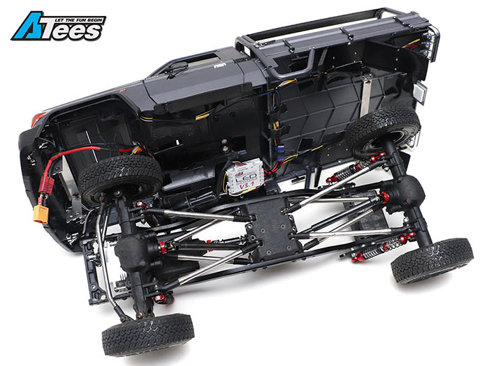
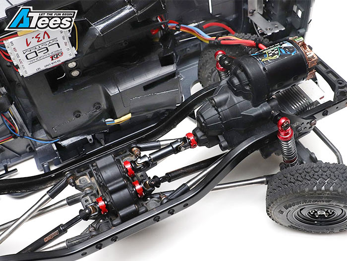
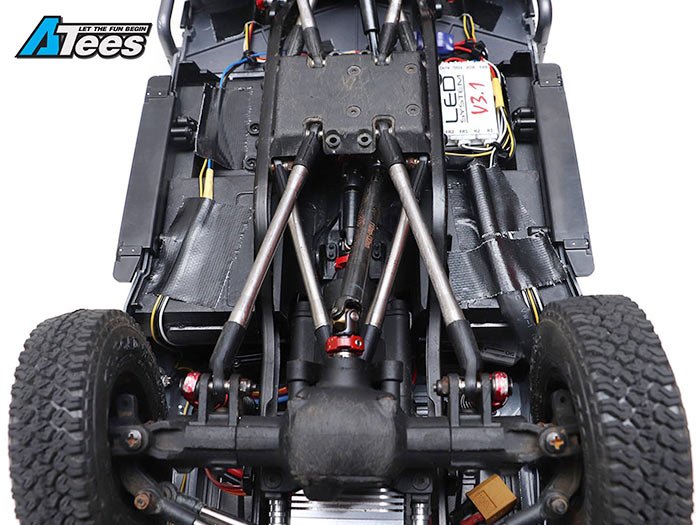
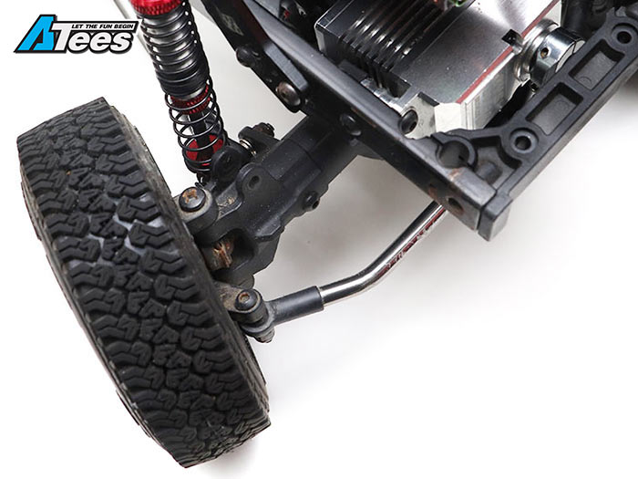
Once the axles are attached to the chassis, I needed longer drive shafts. I got the Boom Racing Voodoo drive shafts (BRQ90279G) on it as the stock CFX kit ones aren’t long enough. This allows me to upgrade the driveline and add extra weight down low and at the same time have better looking scale drivelines.


Shocks
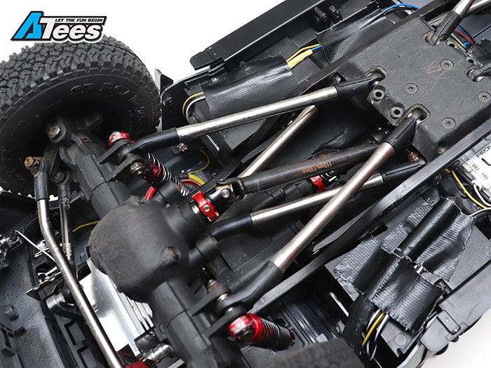
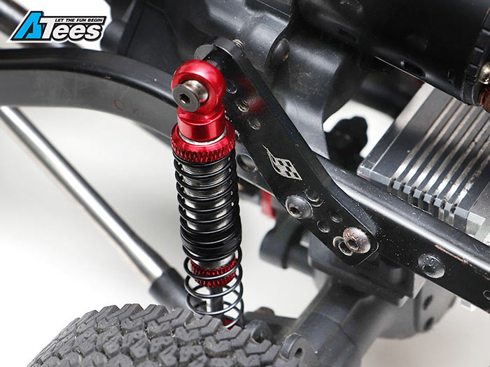
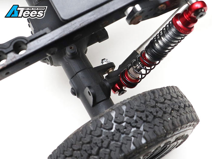
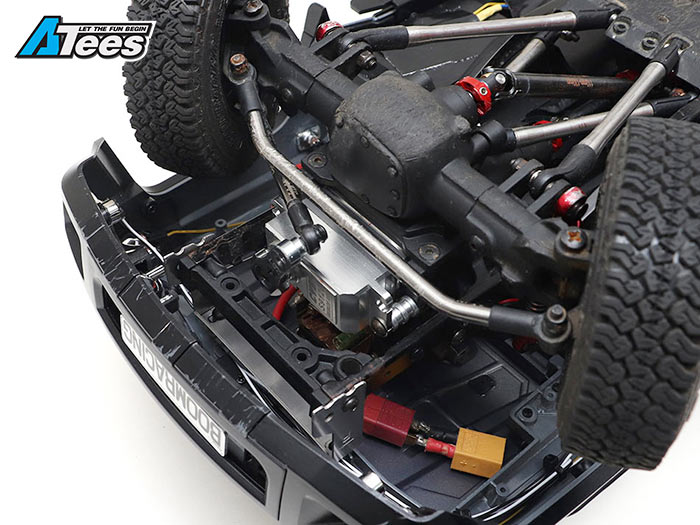
With the chassis rails and the axles attached, the next thing is to mount the shocks to the chassis. From building different types of rigs in the past I found the Boom Racing shock hoops (BRQ90311-2) to be very useful. For the front shock mounts I was able to utilize them by screwing them directly onto the chassis rails. It mounts onto the gearbox fixings. You can see in the picture what position and holes were used to attach the front shock hoop.
For the rear shock mounts, the mounting points need to be as low as possible. The rear bed of the body is almost flush with the chassis rails and there isn’t much room to work with here. To attach them I used the original holes on the chassis rails and the shock hoops but I added a few 4mm spacer in between them. You have the option to remove the rear plastic cross member/plate and just use a few nuts to attach the shock hoops, but I used it to attach the shock hoops.
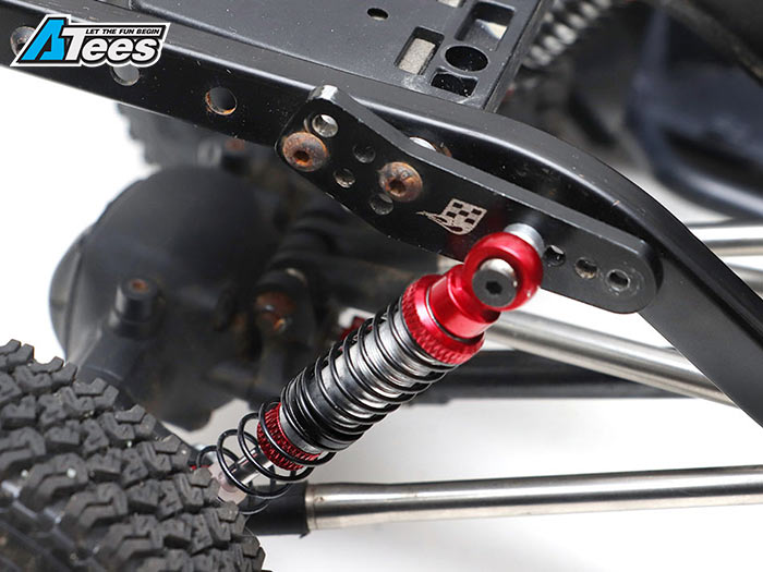
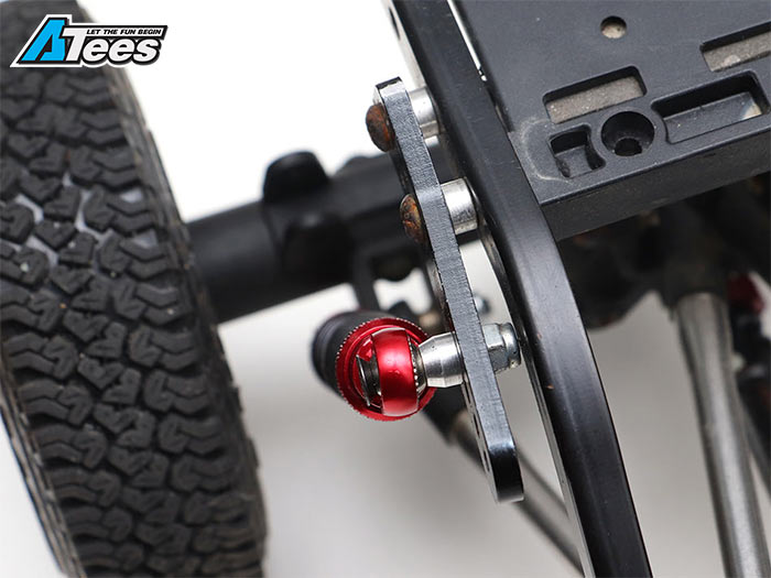
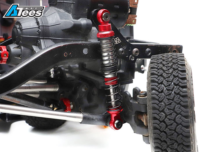
I decided to upgrade the shocks as the shocks from the kit are a bit too soft and I wanted more adjustability for shock settings. I decided to use the Team Raffee Co. 80mm shocks (BRQ90333-80R). They are very affordable and can be adjusted in a number of ways. I picked the 80mm ones which is 10mm longer than the stock 70mm shocks for more suspension travel. Instead of mounting the shocks on the original position, they are now located on the axle link mounts so the shocks can be angled down. You can do this by changing the screw that holds the links in with a longer 25mm flathead screw. To attach the top of the shock to the shock hoop, a spacer is placed in between the two so the shock does not bind with the shock hoop.
Steering Links
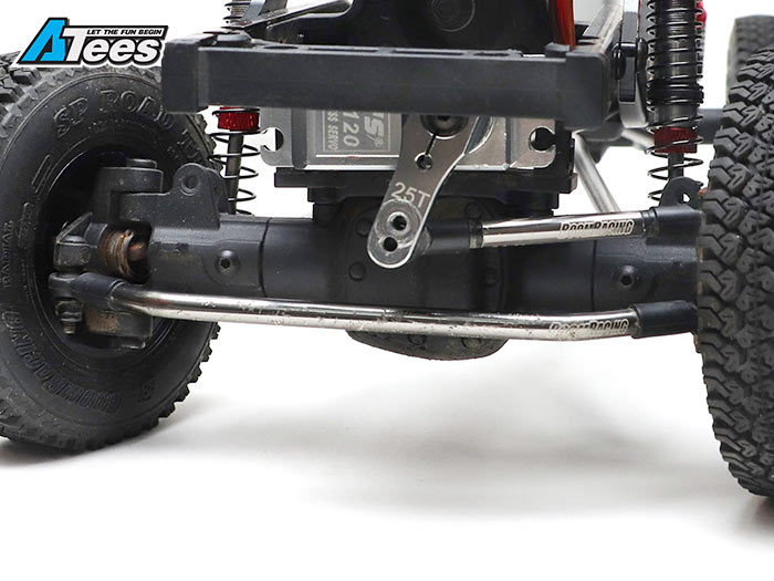
For the steering links I used a Boom Racing Aluminum Link (BRQL5095GM) and bent the ends over slightly. Make sure you insert the set screw inside the link before you put the bend in. The easiest way to do this is to put the ends into the vice and bend it slightly. To link it to the servo, use Boom Racing Aluminum Link (BRQL5020GM). As these are M3 set screws, I used Team Raffee Co. M3 Rod End (BRQ90336) (a small tip: it is easier if you screw the set screw into the rod ends first before screwing into the link).
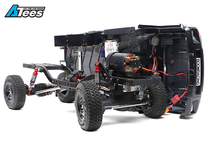
Electronics
Mounting the electronics was a challenge as there isn’t a lot of room under the body. This is a key area of all scale builds and the part that gives most people headaches. But don't stress over it, everything can be done with some DIY thinking, which I believe is the single best essence of our hobby, to problem solve.
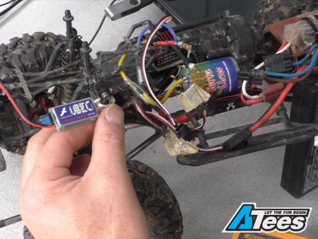
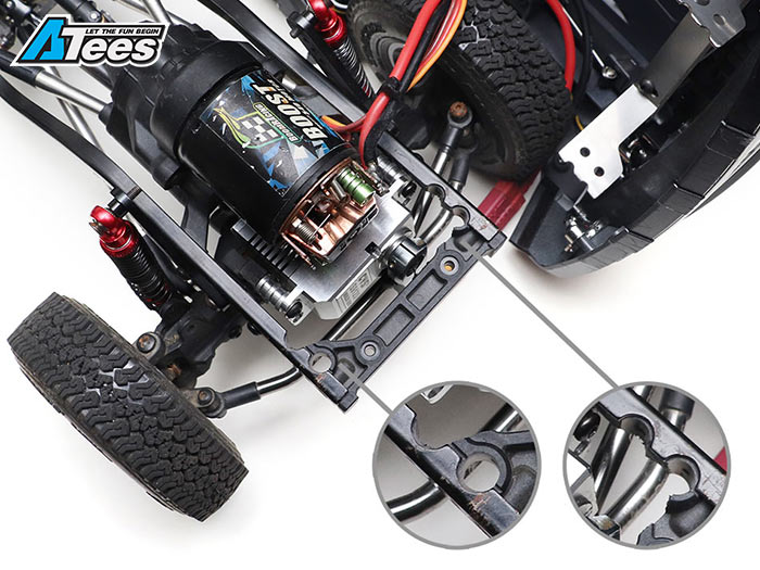
The motor is mounted as normal but the servo had to be moved 10mm forward with some spacers as the gearbox is moved forward. Moving the servo forward I ran into another small issue as the servo horn was hitting the front plastic bumper mount. To solve this, the plastic front bumper mount had to be modified slightly by cutting off the original body mount location to create a bit more room for the servo horn to move. The receiver and ESC I had to install the body first and then stick them to the firewall of the body.
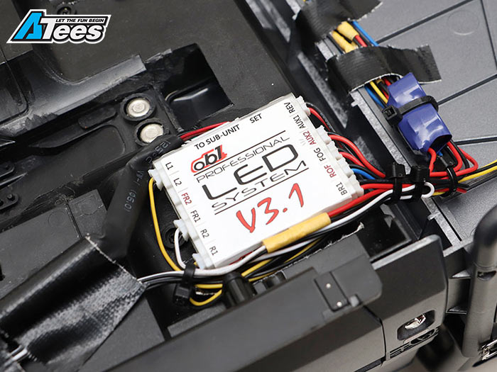
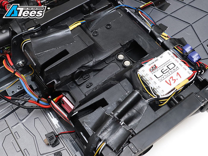
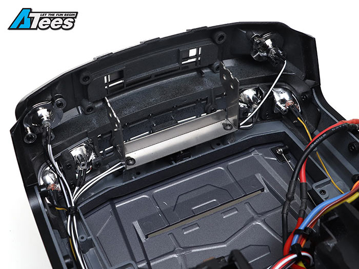
LED Lights
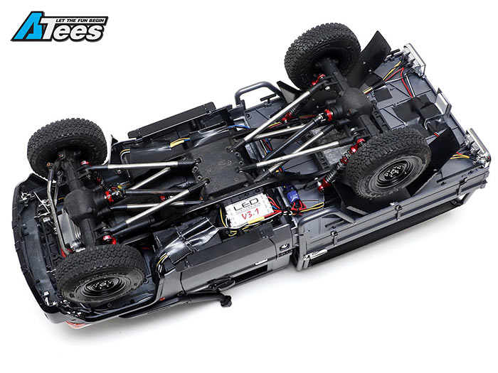
No scale build will be complete without a good set of LED lights to make the build even more realistic. I used two different LED units: an OB1-RC V3.1 LED light unit (OB1/BL-V31) that had all the control options for the lights. We find the OB1 LED light unit to be one of the best. The controls all make sence and its even got a beeping sound for reverse. For the actual LED’s I took all the LED’s off this Killerbody light unit (KB/48706) as the LED’s are made specifically for the LC70. To use the LED’s I cut and rewired all the connectors on the LED’s to be able to plug into the OB1 unit to function properly. Once everything was wired up I stuck it to the bottom of the body.
Tip: if you run out of white plugs for the OB1 LED unit, you can use the plugs from other LED units that use the same white plugs by cutting them off and soldering them to the OB1 unit.

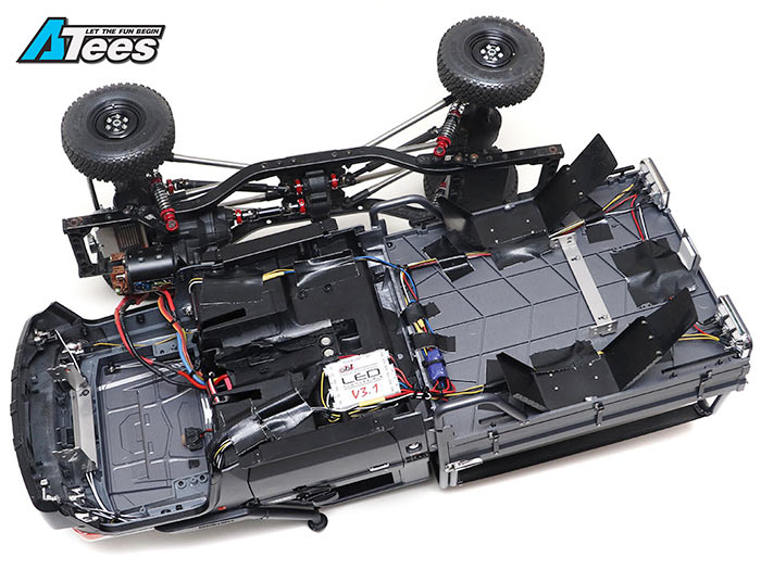
Attaching the LC70 body to the custom MST CFX chassis
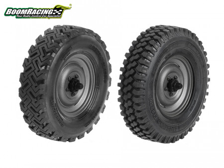
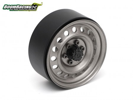
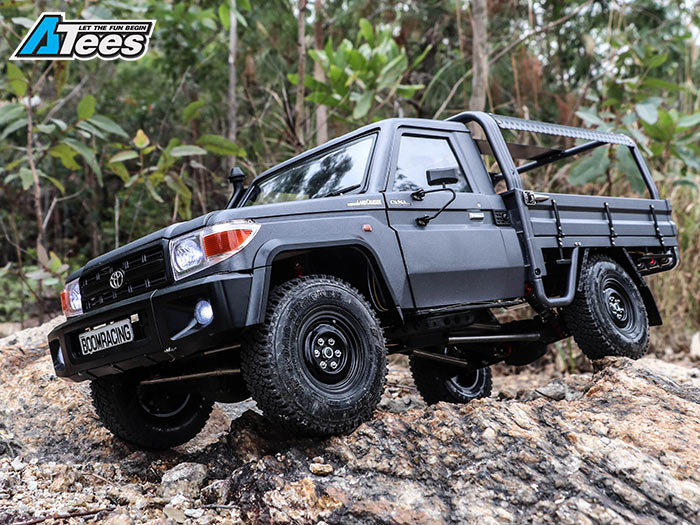
First I attached the Killerbody metal body mounts (KB/48671) to the body. Then to attach the completed LC70 body with interior to the chassis I did a few modifications to the interior of the body to be able to get the body sit low enough to the chassis for the desired ride height. In the pictures you will see the area that was trimmed and cut off for the body to sit snug with the chassis. Then I attached the Boom Racing 1.55" Steelie wheels, front (BRW780907FBK) rear (BRW780907RBK) and 1.55" SP Road Tracker tires (BRTR15501).

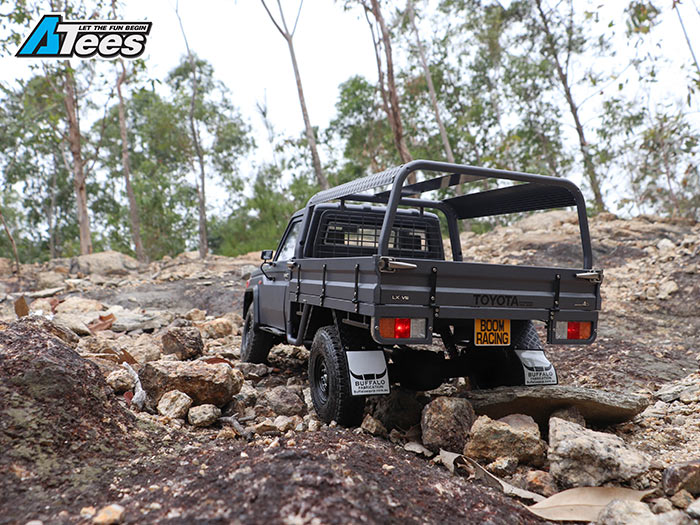
Extras
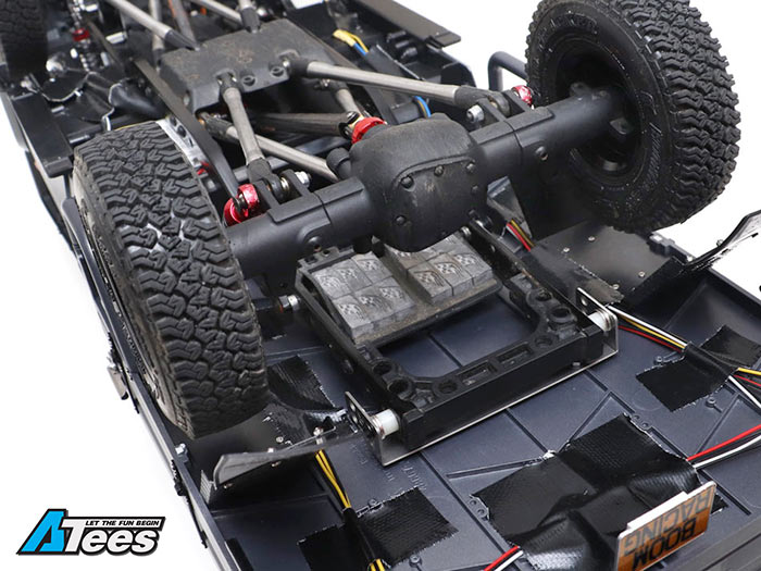
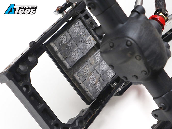
I added some Boom Racing Lead Weights (BRW780900H) onto the back plate to give the rear end a bit of extra weight. This is just down to your own preference.
For those that like to DIY things there is another more affordable option where you can DIY your own links to the exact lengths you need. The link is available below. I measured out the rough lengths to make it easier for you if you wanted to do down that option and here they are:
Team Raffee Co. DIY Aluminum Full Link Set (TRC/302352)
Link Measurements:
- Front Upper Link - 70mm
- Rear Upper Link - 80mm
- Front Lower Link - 85mm
- Rear Lower Link - 90mm
- Steering Link – 95mm & 20mm
Note: The above measurements are slightly longer then needed as the DIY links come with different rod ends and you can always shorten the link a bit more if they are too long.
List of parts available to build it:
- 1/10 MST CFX Chassis #MST/532148
- 1/8 MST Chassis Rail #MST/310093
- Boom Racing Voodoo Shaft #BRQ90279B
- Boom Racing 313mm Stainless Steel Link Set #BR967010S
- Boom Racing Mixed Rod Ends #BRWM4RECOMBO
- Boom Racing Voodoo CVD Drive shafts #BRQ90279G
- Shock Hoop Extension #BRQ90311-2
- Team Raffee Co Shocks #BRQ90333-80R
- Boom Racing Link #BRQL5095GM
- Boom Racing Link #BRQL5020GM
- Team Raffee Co Rod Ends #BRQ90336
- Boom Racing Lead Weights #BRW780900H
- OB1-RC V3.1 LED Light Unit #OB1/BL-V31
- Killerbody LC70 LED Light unit #KB/48706
- Killerbody Body Mount # KB/48671
- 1.55 Front Boom Racing Yota Wheels #BRW780907FBK
- 1.55 Rear Boom Racing Yota Wheels #BRW780907RBK
- 1.55 Boom Racing Tires #BRTR15501
- *Team Raffee Co DIY Link Set with Rod Ends #TRC/302352
ByRicky M
Tags :MST, CFX, CFX-W, LC70, Scale Crawler, Killerbody, Boom Racing
Share:http://asiate.es/read?l=E15_98CEYGD